Manual
HD Legacy Pumper
Version 2022.09.26 Early Access
Open Legacy Pumper Changelog
Work in Progress
INDEX:
- Early Access Notes
- 0) Welcome
- 1) Specifications
- 2) Frequently Asked Questions
- 3) Main Menu (Public)
- 4) Main Menu (Owner)
- 5) Operation
- 6) Equipment
- 7) Chat Commands / Gestures
- 8) Textures
- 9) HD Theme Box 3
- 10) Script API
- 11) Feedback
Early Access Notes
The HD Legacy Pumper is available as Early Access Version.
This version gives early access to the upcoming HD Legacy Pumper.
It is not yet feature complete and more things will be added with free updates.
You can vote for your favorite development topic with the Survey to raise its priority.
This version gives early access to the upcoming HD Legacy Pumper.
It is not yet feature complete and more things will be added with free updates.
You can vote for your favorite development topic with the Survey to raise its priority.
Disabled Features
- - Modular HUD support for Officer
- - some Tablet features
- - full Emergency Light Customization
- - ThemeBox3 Support
- - Custom Specular & Bump Map Support
- - Land Impact Optimization
- - Sound Updates
0) Welcome
Thank you for purchasing the Legacy Pumper.
If you are experiencing any problems with your product, please be sure that you have read this manual in its entirety and you fully understand its contents.
If at any point this manual does not help you please join the HD Emergency Equipment and supplies group and ask your question within the group chat.
Alternatively you can also join the HD Discord Server and ask your question in the #helpdesk channel.
We hope you enjoy your product from HD Emergency! Thank you for the support!
1) Specifications
General
- Full Mesh Build- Seats up to Six Avatars
- Working Park Lights, Headlights, High Beams, Taillights, Turn Signals and Hazard Lights
- Automatic Transmission with simulated Acceleration Model
- Parking Brake to switch Physics on or off
- Opening Doors and Cabinets
- Working Power Windows
- Animated Windshield Wipers
- Compatible with the NTBI Global Fuel System
50.0 Gallon Diesel Fuel Tank
Maximum 160.0 miles to a tank
3.20 Miles Per Gallon
- Compatible with the HD Exhaust Removal SystemMaximum 160.0 miles to a tank
3.20 Miles Per Gallon
- Compatible with the HD Electric Charging System
Emergency Lights System
- HD Box Lightbar and raised roof Lightbar Pods- Wig-Wag Front Flashers
- Flashers on all sides
- Rear Beacons
- customizable with preset color selections
- Side Scene Light with Extendable Pole
- Rear Hosebed Scene Lights
- optional Front Brow Lights
- optional Front Rotoray
- Traffic Director Lightbar
Electrics System
- simulated electrics system- each element has its own power consumption
- cab can be raised and drained batteries can be replaced
Sound Setup
- airhorn and electrical horn- wail, yelp, priority, powercall, high/low sirens with manual switch
- with option for custom Sound UUIDs
- mechanical Q-Siren with manual and auto mode
Equipment
- Four Handheld Lights- Medical Jumpbag
- Tool Box
- Hard Case Box
- Ground Work Lights
- Rescue Basket
- Two Wheel Chocks
- various Hand Tools
- Chainsaw and Circular Saw
- Caution Tape and Duct Tape
- Road Flares
- Junction Box (60m cable reel)
- Binding Agent
- Two Foam Concentrate Jugs
- Foam Refill Hose
- Electrical and Gasoline Fan
- Two Fire Extinguishers
- Traffic Pylons
- Draft Float
- Six SCBA Refills
- Ground Ladder (14 foot)
- Extension Ladder (24 foot)
Fire Hose
- Bumper Line- Two Crosslays
- Two Attack Lines
- Small Supply Line
- Large Supply Line
- Four sections of Suction Hose
Pump System
- optional Front Bumper Large Intake- Driver and Passenger Side Large Intake
- Passenger Side Small Intake
- Two Driver Side Small Discharges
- Two Crosslay Discharges
- Two Rear Small Discharges
- Smoothbore and Combi-Nozzle Option
- extendable Master Stream / Deckgun with Fog Pattern
- adjustable Pump Limit 750/1000/1250/1500/1750/2000 GPM
- adjustable Water Tank 500/625/750/875/1000/1125/1250 gallons
- adjustable Foam Cell 10/20/30/40/50/60 gallons
- adjustable Foam Injection Pump 3/6/9/12/15 GPM
- Water and Foam Refill Towers
- Foam Refill with Suction Wand
Customization
- user-friendly Customize HUD- Twelve standard HD Paintjobs
- Twelve plain color Paintjobs with custom RGB color option
- Full Paintjob Templates
- Thirty Decal Texture Spots
- Twelve Rear Chevron Patterns
- Optional Paintjob Overwrite Areas
- Truck Unit Number 1 to 9999
- Fenderette and Flasher Housing Color
- Front Grill and Headlight Housing Color
- Front Bumper Color and Chevron Option
- Cab Window Color Tint Option
- Wheel Cap Color
- License Plates
- Cab Interior Color Options
- Seat Cushion Color Option
- with easy to use interior presets
- Hosebed Tarp Colors and Options
- Changeable Equipment Colors
- optional Cab Front Grab Handles
- optional Cab roof mounted A/C Condernser Unit
- optional Cab side mounted Water Level Indicator
- optional Front Bumper Bell and Marker Rods
- optional Rear mounted Flag with Texture Option
- optional Rear Large Mudflap
- optional Rear Side Markers
2) Frequently Asked Questions
Q: How do I start the Legacy Pumper?
A: Switch on the battery master switch. It's the red switch below the driver seat.
Switch on the Ignition Switch on the right side below the steering wheel.
Click on the Engine Start switch next to the Ignition Switch.
Q: How do I turn on the pump?
A: Come to a complete stop and apply the parking brake.
Make sure the engine is running as outlined in Question 2.
Select 'N' for Neutral on the gear shifter. Observe that active gear switches to N.
Click on the yellow Pump Power Shift Lever on the left side below the steering wheel and make sure it points down at 'Pump'.
Select 'D' for Drive on the gear shifter. Observe that active gear switches to 4.
Q: How do I raise / lift the cab?
A: Open the maintenance hatch on the passenger side of the pump panel by clicking on it.
Click on the left flip switch and make sure it points up towards 'Controls Active'.
Click on the right flip switch to raise the cab.
If the main battery switch is turned off then the cab will only raise slightly each time and will require several clicks to fully raise.
Q: How do I replace the batteries?
A: Raise the cab as outlined in the previous Answer.
Click on one of the four batteries to remove it.
Confirm the menu dialog to remove the battery.
Rez the supplied Battery Shelf in-world and click on one of the cardboard boxes to pick it up.
While carrying the cardboard box either click on the box to place the box on the ground.
Alternatively switch to mouselook and click on the ground close to your avatar to place the box there.
Click on the box on the ground and select 'Open' in the Interaction Menu to open the box.
Click on the box again and select 'Grab Item' in the Interaction Menu to grab the spare battery.
While carrying the spare battery click on an empty spot on the Legacy Pumper battery tray to place the spare battery.
Optionally click on the empty cardboard box and select 'Recycle' in the Interaction Menu to remove the box.
The Battery Shelf also has a variant with three Battery Boxes. It's available inside the shelf prim contents.
Those can be placed on your own shelf and can be linked to other objects.
Q: How do I change the pump specifications?
A: Click on the Pump Specifications Plaque on the Driver Side of the pump panel.
It is located on the bottom left side of the pump panel right below the HD Foam Master Panel.
Q: How can I apply decals?
A: Click on the cab to bring up the Main Menu.
Select 'Customize' and then 'Decal Mode' in the menu. Observe that a couple of pointers with blue arrows will appear.
Click on any of the pointers and enter your Decal Texture UUID in the text box and select 'Submit'.
Q: Why can I not pump more than 500 GPM when not connected to a hydrant or other water supply?
A: This is an intentional limitation.
The amount of water the pump can draw from the tank is limited by the diameter of the connecting pipe and valve.
Most commonly the Tank To Pump pipe has a diameter of 3 Inches.
That limits the flow of water to 500 GPM max.
Q: Why is there a warning sound when I release the parking brake?
A: The warning sound is linked to the Do Not Move Apparatus warning light on the ceiling of the cab.
The warning is interlocked with the parking brake and is triggered if any of the following is the case:
- any of the cab doors open
- any of the roll up doors raised
- rear compartment doors open
- scene lights at pump panel raised
- deckgun raised
3) Main Menu (Public)
The Main Menu can be brought up by clicking on the Cab of the vehicle.
The following buttons are available to everyone with Crew Access Level.
Only the owner of the vehicle can change additional Options.
The following buttons are available to everyone with Crew Access Level.
3.1 Manual
This button will give you a link to the online Manual, which you are reading right now.
3.2 Report
This will send a text report to your local chat with the vehicle status.
The report shows you who last drove the vehicle and the time at which they sat down.
It also shows the same information for the last officer and pump panel operator.
It will also display the fuel system status and total driven miles.
Additionally it includes information about the battery status and electrical system.
3.3 Modular HUD
This vehicle is compatible with the HD Modular HUD, which is distributed by a centralized server within Second Life.
To receive a copy of the latest version simply select 'Modular HUD' in the main menu of your vehicle.
Alternatively you can click on the Modular HUD pamphlet in the glove box of the cab.
Or you can select the Modular HUD button on the Tablet inside of the cab.
The Modular HUD allows you to control all of the functions of your vehicle.
An automatic sync to your vehicle is performed when attaching the HUD or sitting down.
3.4 Gear HUD
This vehicle is compatible with the HD Gear HUD, which is distributed by a centralized server within Second Life.
To get a copy of the latest version simply select 'Gear HUD' in the main menu of your vehicle.
Alternatively you can click on the Gear HUD book in the glove box of the cab.
Or you can select the Gear HUD button on the Tablet inside of the cab.
The Gear HUD handles most of the equipment on the HD Vehicles.
You will not be able to use the compatible equipment without having the Gear HUD attached.
For more information on the features of the Gear HUD please consult the HD Fire System 2 Manual.
3.5 Drive Config
The Drive Configuration Menu offers various settings to adjust the driving behavior.
The owner of the vehicle can set his own preferences while everyone else shares their settings.
These three settings can be changed by anyone with access to the vehicle:
Only the owner of the vehicle can change additional Drive Configuration Settings.
The owner of the vehicle can set his own preferences while everyone else shares their settings.
These three settings can be changed by anyone with access to the vehicle:
3.5.1 Speed Retain
This button activates or disables the Speed Retain Mode.
The Speed Retain Mode will retain the speed in MPH after the gas pedal / forward arrow key is no longer pressed.
To switch the vehicle to regular free rolling you can tap the brakes / down arrow key once.
This driving assistant can be very helpful to maintain a constant speed without tapping the forward arrow key.
3.5.2 Bad Road Fix
This button activates or disables the Bad Roads Fix overwrite setting.
The Bad Roads Fix will skip the ray-casting process for airborne detection.
Without airborne detection the driving experience will be less realistic.
The vehicle can now be controlled while the wheels do not touch any surfaces.
It might be necessary to activate the Bad Roads Fix for driving on Roads with a faulty Physics Shape.
3.5.3 Transmission
This button switches the Transmission between Realistic and NextGen Mode.
In realistic mode the transmission will switch in this order: R - N - D - 2 - 1.
This resembles a regular automatic transmission.
While in NextGen mode the gear order is changed to: R - N - 1 - 2 - 3 - 4 - 5 - 6.
This is closer to the way the NextGen Trucks operate.
For both modes:
1st gear limits the speed to circa 15 MPH.
2nd gear limits the speed to circa 35 MPH.
Drive gear limits the speed to circa 80 MPH.
The Parking Mode can be activated on the Modular HUD to half the top speed.
Only the owner of the vehicle can change additional Drive Configuration Settings.
3.6 Options
3.6.1 Restock All
This will restock all equipment of the vehicle in case any of it was lost.
3.6.2 Restock SCBA
This will restock all of the spare SCBA Cylinders in the wheel well compartments.
Restocking SCBA Bottles requires a nearby SCBA Station.
Restocking SCBA Bottles requires a nearby SCBA Station.
3.6.3 Kill Fires
This button will allow you to kill any and all HD Fires within the same region of the apparatus.
This is extremely useful when a situation gets out of hand.
Only the owner of the vehicle can change additional Options.
4) Main Menu (Owner)
The Main Menu can be brought up by clicking on the Cab of the vehicle.
The following buttons are available to only the owner.
The following buttons are available to only the owner.
4.1 Kick
This button allows you to eject an avatar from the vehicle.
4.2 Access
This menu allows you to change the vehicle's permissions on who can operate it.
There are two levels of access: Crew and Passenger.
Crew includes the Driver, Officer and Pump Operator.
Passenger only allows to sit in any of the passenger seats.
You may set each to Owner, Group or Everyone.
Group includes all members of the group that the truck is set to.
To further restrict the access the truck supports the use of a whitelist.
With the whitelist you can add specific people to the Crew role.
Only usernames can be used for the whitelist.
For accounts without a last name you only have to enter the first name.
Display Names are not supported as they are subject to frequent changes.
The whitelist will not automatically update if someone changes their username.
4.3 Options
4.3.1 Remove Scripts
This button will remove all scripts from the vehicle.
Removing the scripts can not be undone and will disable any interaction with the vehicle.
A separate dialog will ask for confirmation before all scripts are removed.
Removing scripts can help with managing the performance impact during events or when using the vehicle for display purposes.
Removing the scripts can not be undone and will disable any interaction with the vehicle.
A separate dialog will ask for confirmation before all scripts are removed.
Removing scripts can help with managing the performance impact during events or when using the vehicle for display purposes.
4.3.2 Script API
This button lets you set the channel for the Script API.
For detailed information about the available commands please check the Script API section.
For detailed information about the available commands please check the Script API section.
4.3.3 Clipboard URL
This button lets you set a website URL to be used for the Incident Report Clipboard in the glove box.
A link to the website is offered when someone clicks on the Clipboard.
This can be helpful when a 3rd Party online incident report tool is used for your Fire Department.
A link to the website is offered when someone clicks on the Clipboard.
This can be helpful when a 3rd Party online incident report tool is used for your Fire Department.
4.3.4 Odometer
This button lets you manipulate the Odometer readout by entering a new driven miles value.
The value is shown on the Dashboard and for the Report feature.
The value is shown on the Dashboard and for the Report feature.
4.3.5 Rename
This button lets you enter a new object name for your vehicle.
4.3.6 Sounds
This button brings up the Sound Customization Menu.
The following sounds can be changed:
- Siren Wail
- Siren Yelp
- Siren High/Low
- Siren Priority
- Siren Powercall
- Siren Manual
- Auto Siren
- Airhorn
- E-Horn
- Backup Warning
To change any of the sounds simpy select it in the menu and enter the UUID of the replacement sound.
You can leave the input field blank to reset the sound to the default one.
4.4 Drive Config
The Drive Configuration Menu offers various settings to adjust the driving behavior.
The Public Settings can be changed by anyone with Crew Access to the vehicle.
These five settings can only be changed by the owner of the vehicle and apply to everyone driving the vehicle:
The Public Settings can be changed by anyone with Crew Access to the vehicle.
These five settings can only be changed by the owner of the vehicle and apply to everyone driving the vehicle:
4.4.1 Fuel System
This button activates or disables the NTBI Global Fuel System (GFS).
4.4.2 Electrics
This button activates or disables the Electrics System.
When active then each active electrical component will consume energy.
If the vehicle is turned off then all energy is supplied by the batteries.
The diesel engine will charge the batteries.
The charge rate is increased if the vehicle is stationary and High Idle is active.
The HD Electric Charging System can be used to charge the batteries at the Fire Station.
4.4.3 ARO System
This button opens the menu for the Anti-Roll-Over (ARO) System.
The ARO System has 3 settings. You can select: Full, Support, Off
Based on the active setting this assistant will help to prevent roll-over accidents.
The ARO System has 3 settings. You can select: Full, Support, Off
Based on the active setting this assistant will help to prevent roll-over accidents.
4.4.4 Turn Radius
This button opens the menu to change the Turn Radius.
The Turn Radius has 5 possible settings: Very Tight, Tight, Moderate, Wide, Very Wide
By default the Turn Radius is set to Tight.
The Turn Radius has 5 possible settings: Very Tight, Tight, Moderate, Wide, Very Wide
By default the Turn Radius is set to Tight.
4.4.5 Brake Strength
This button opens the menu to change the Brake Strength.
The Brake Strength has 5 possible settings: Very Strong, Strong, Moderate, Weak, Very Weak
By default the Brake Strength is set to Moderate.
The Brake Strength has 5 possible settings: Very Strong, Strong, Moderate, Weak, Very Weak
By default the Brake Strength is set to Moderate.
4.5 Customize
4.5.1 Sync HUD
This button allows you to connect and synchronize the vehicle with the HD Legacy Customize HUD.
A copy of the compatible Customize HUD is available in the delivery box for your vehicle.
A copy of the compatible Customize HUD is available in the delivery box for your vehicle.
4.5.2 Decal Mode
This button acts as a switch to activate and deactivate the Decal Mode.
This will show little blue pointers with arrows for all decal surfaces.
The flag contains information for the ideal aspect ratio and supported texture resolutions.
Simply click on any of the pointers and enter your texture UUID in the dialog input to apply it.
It is advised to always use the lowest possible resolution for your decals to help reduce the visual impact.
4.5.3 EM Lights
This button opens the Emergency Lights Color menu.
This is a placeholder for the Full Emergency Light Customization which will be added with an update.
The following Emergency Lights can be changed:
- Lightbar
- Flashers (front, side and rear)
- Rotoray
- Beacon Left
- Beacon Right
- Traffic Director
Additionally a special Color Mode can be activated.
Selecting 'Color Mode' in the EM Lights Menu will turn the mode on and off.
The Color Mode can only be active while the Emergency Lights Master switch is turned off.
Once active it will highlight the Lightbar, Flasher and Rotoray surfaces.
Clicking on one of the highlighted surfaces will bring up the Color Menu to change the individual color.
Some of the surfaces are grouped and will change together.
4.6 Survey
The Survey Menu lets you vote on upcoming features in development.
The Survey results will help to prioritize the most popular features.
More details about the available choices:
Assist HUD
EM Light HUD
ThemeBox
Custom Maps
Land Impact
Sounds
Tablet
Other
The Survey results will help to prioritize the most popular features.
More details about the available choices:
Assist HUD
Modular HUD support while sitting in the Officer Seat.
EM Light HUD
Full Emergency Lights Customization via HUD.
This includes:
- ability to change patterns
- ability to change individual colors
- ability to use custom color RGBs
This includes:
- ability to change patterns
- ability to change individual colors
- ability to use custom color RGBs
ThemeBox
Compatibility with HD ThemeBox 3 to quickly apply full customization setups.
Custom Maps
Custom bump map and specular map support for custom paintjobs.
Land Impact
Reducing the Land Impact.
Sounds
New and improved Sounds.
Tablet
Make the Cab Interior Tablet fully functional.
Other
Enter your own ideas and topics.
Suggested features should have a limited scope and complexity in order to be considered for the Early Access Updates.
Suggested features should have a limited scope and complexity in order to be considered for the Early Access Updates.
5) Operation
5.1 Cab Interior
The interior of the cab has several interactive control elements.
Those can be used by the Driver, Officer or anyone with Crew Access permission.
The following features are available:
Those can be used by the Driver, Officer or anyone with Crew Access permission.
The following features are available:
5.1.1 Driver Seat
Driver - Below Seat
Battery Switch
The Battery Master Switch has two positions:
Off: Disconnects the entire electrical system to all batteries.
On: Connects the entire electrical system to all batteries.
It is advised to disconnect the batteries while the Legacy Pumper is parked at the Fire Department to prevent discharging the batteries.
Off: Disconnects the entire electrical system to all batteries.
On: Connects the entire electrical system to all batteries.
It is advised to disconnect the batteries while the Legacy Pumper is parked at the Fire Department to prevent discharging the batteries.
Charge Monitor
The Charge Monitor shows you the state of the electrical system.
The 10 Bars indicate the remaining Voltage on all installed batteries.
The Status Light has three states:
Blue: Batteries are being charged
Amber: Batteries are being discharged
Red: Electrical System fault.
The 10 Bars indicate the remaining Voltage on all installed batteries.
The Status Light has three states:
Blue: Batteries are being charged
Amber: Batteries are being discharged
Red: Electrical System fault.
Power Seat Controls
The Power Seat Controls are only decorative and not functional.
Driver - Front
Dashboard Status Lights
The Status Lights display has several indicator and warning lights.
Top Row:
Top Row:
- Left Turn Signal (click to toggle)
- Diesel Engine Fault
- Battery Low Warning
- High Beams Indicator
- Fuel Tank Low Warning
- Engine Brake Engaged
- Right Turn Signal (click to toggle)
- Cabinet Ajar Warning
The Cabinet Ajar Warning will be illuminated if any of the Roll Up Compartment Doors are in the up position.
It will also illuminate if the rear Double Compartment Doors are ajar.
- Door Ajar Warning
The Door Ajar Warning will be illuminated if any of the four Legacy Cab doors are ajar.
- Parking Brake Set
- Oil Pressure Warning
- Coolant Temperature Warning
- Battery Switch On Indicator
Dashboard Gauges
The Legacy Dashboard has eight gauges to give you vital vehicle information.
- Tachometer
- Speedometer with integrated Odometer
- Voltmeter
- Fuel Tank Level
- Engine Oil Pressure
- Primary Air Pressure (front)
- Secondary Air Pressure (rear)
- Transmission Fluid Temperature
Pump Power Shift
The Pump Power Shift Panel is located towards the left side of the steering wheel column.
Instructions to operate the Power Shift Lever are printed on the panel.
Instructions to operate the Power Shift Lever are printed on the panel.
Engine Switch Panel
The Engine Switch Panel is located towards the right side of the steering wheel column.
It has five switches:
It has five switches:
- Ignition
Switch Ignition to On in order to start diesel engine.
The indicator light next to the switch will illuminate if the Ignition is on.
Make sure the Battery Master Switch is set to on if Ignition fails to switch.
The Dashboard Gauges and Status Lights will run a self diagnostics routine when the Ignition is switched on.
To shut down the engine turn off the Ignition.
- Engine Start
Depress the Engine Start Rocker Switch to start the Diesel Engine.
The Ignition must be switched on in order to start the engine.
- Panel Lights
Activates panel lights for the Dashboard Gauges, Gear Shifter and all Switch Panels.
- Engine Fan Engage
Activates the Engine Fan while the Diesel Engine is turned off.
- Hazard Lights
Steering Wheel
Clicking on the center of the Steering Wheel will activate the horn.
If the E-Horn Switch is active then an electronic horn will sound.
Otherwise the Airhorn will be activated.
If the E-Horn Switch is active then an electronic horn will sound.
Otherwise the Airhorn will be activated.
Multilever
Clicking on the Multilever on the left side of the Steering Wheel Column will activate the High Beams.
If the Headlights are turned On then the Multilever will switch the High Beams On / Off.
If the Headlights are turned Off then the Multilever will activate the High Beams for as long as the Multilever is clicked.
If the Headlights are turned On then the Multilever will switch the High Beams On / Off.
If the Headlights are turned Off then the Multilever will activate the High Beams for as long as the Multilever is clicked.
Driver - Engine Cover
Gear Selector
The Legacy Pumper is equipped with two transmission modes: Realistic and NextGen.
You can set the Transmission via: Open Main Menu > 'Drive Config' > 'Transmission'.
In realistic mode the transmission will switch in this order: R - N - D - 2 - 1.
The following buttons will be visible on the transmission panel: R, N, D, TGL, 2 and 1.
This mode resembles a regular automatic transmission.
While in NextGen mode the gear order is changed to: R - N - 1 - 2 - 3 - 4 - 5 - 6.
The following buttons will be visible on the transmission panel: R, N, 4, TGL, ▲ and ▼.
This mode is closer to the way the NextGen Trucks operate.
The Legacy Transmission works as a demand based model.
The requested gear is displayed on the left side as SELECT.
The transmission will fulfill the request if possible and display the active gear on the right side as ACTIVE.
Gears can only be selected while the engine is running.
The HD Modular HUD will only display the requested gear.
Button Functions:
- R - Reverse Gear
- N - Neutral Gear
- D - Drive Gear, transmission will automatically shift along full range
- 1 - 1st Gear Override to limit top speed to ca. 15 MPH
- 2 - 2nd Gear Override to limit top speed to ca. 35 MPH
- 4 - direct shift to 4th Gear for Pump Mode
- ▲ - Upshift Gear
- ▼ - Downshift Gear
- TGL - reserved for future function
Parking Brake
Releasing the Parking Brake will activate the Physical Mode for the vehicle.
The following systems are interlocked with the Parking Brake:
The following systems are interlocked with the Parking Brake:
- Ground Lights
- will only illuminate if parking brake is applied.
- Roto-Ray Emergency Light
- will not spin if parking brake is applied to avoid personal injury.
- Wig-Wag Emergency Lights
- will not illuminate if parking brake is applied.
- Do-Not-Move Warning Light
- will only activate if parking brake is released.
Q-Siren
The Q-Siren Panel controls the mechanical siren.
A secondary panel is available for the Officer Seat.
Q-Siren will activate the siren for as long as the button is depressed.
Auto Siren will automatically operate the Siren along its full range.
A secondary panel is available for the Officer Seat.
Q-Siren will activate the siren for as long as the button is depressed.
Auto Siren will automatically operate the Siren along its full range.
Emergency Lights
The Legacy Pumper is equipped with a Master Switch and seven Emergency Light Selector Switches.
The Master Switch must be set to On in order to activate the Emergency Lights.
The Selector Switches can be used to enable and disable individual Emergency Lights.
Selector Switches:
The Master Switch must be set to On in order to activate the Emergency Lights.
The Selector Switches can be used to enable and disable individual Emergency Lights.
Selector Switches:
- Lightbar
- controls the main lightbar and two lightbar pods on the roof of the cab
- Warn Front
- controls the forward facing Flashers above the Headlights
- Warn Side
- controls the driver and passenger side Flashers on the Bumper and above the wheel wells on the Cab and Box
- Warn Rear
- controls the six rear facing Flashers on the backside of the Box
- Rear Beacon
- controls the two spinning beacons on the top rear of the Box
Notice: due to a SL bug the beacons will sometimes fail to spin, to fix the issue you can right-click on the vehicle
- Wig-Wag
- controls the forward facing Wig-Wag Flashers that are integrated with the Headlights
Notice: the Wig-Wags are always off if the Parking Brake is applied
- Roto-Ray
- controls the forward facing Roto-Ray above the grill
Notice: the Roto-Roy will not spin if the Parking Brake is applied to avoid personal injury
Engine Brake
This feature will be added with a future update.
High Idle
This will increase the idle RPM when the vehicle is stationary.
A higher idle RPM will raise the Alternator output and increase the charge rate of the Batteries.
The High Idle Switch can only be activated if the 'OK to Engage Hi-Idle' indicator light is illuminated.
Conditions to engage High Idle:
A higher idle RPM will raise the Alternator output and increase the charge rate of the Batteries.
The High Idle Switch can only be activated if the 'OK to Engage Hi-Idle' indicator light is illuminated.
Conditions to engage High Idle:
- - Diesel Engine is on
- - Transmission set to N
- - Parking Brake is applied
- - Pump Power Shift set to Road
Headlights
This will activate the Headlights with the Low Beam setting.
The High Beams are activate with the Multilever on the Steering Wheel column.
The High Beams are activate with the Multilever on the Steering Wheel column.
Marker Lights
This will activate the Marker Lights.
These are the smaller amber and red Position Lights on the Cab and Box.
These are the smaller amber and red Position Lights on the Cab and Box.
Wipers
This will activate the windshield wipers.
Notice: the intermittent Wiper control slider is only decorative.
Notice: the intermittent Wiper control slider is only decorative.
Power Windows
The Driver Side Window and Pass Side Window switches will control the power windows for the front doors.
Generator PTO
The Legacy Pumper is equipped with an on-board hydraulic driven Electrical Generator.
It powers a cable reel with a quad power strip that is stored in the rear-most driver side compartment.
The Generator PTO is connected to the drive shaft and will power the hydraulic pump.
The Generator PTO can only be activated if the Diesel Engine is on and running at below 1100 RPM.
The Gen PTO Engaged indicator light will illuminate if the Generator PTO is engaged.
The Generator On/Off Switch will turn the Generator itself on and off.
The Generator can only be turned on if the Generator PTO is engaged.
Tablet
The Legacy Pumper is equipped with a tablet mounted on a swivel arm.
It can be used by either the Driver or the Officer.
Clicking on the backside of the Tablet will turn it towards the avatar.
Detailed information about the Tablet is available here.
It can be used by either the Driver or the Officer.
Clicking on the backside of the Tablet will turn it towards the avatar.
Detailed information about the Tablet is available here.
Driver - Overhead
Switch Panel
E-Horn / Airhorn
If active then clicking on the center of the Steering Wheel will sound the Electronic Horn instead of the Airhorn.
Ground Lights
This activates the Ground Lights below the Box.
Notice: the Ground Lights will be turned off if the Parking Brake is released.
Brow LightNotice: the Ground Lights will be turned off if the Parking Brake is released.
This activates the forward facing Brow Light above the windshield.
Scene Left / Right
This activates the Left / Right extendable Scene Light that is mounted on the Pump Panel.
Clicking on the Scene Light Pole will extend the Scene Light Upwards.
Clicking on the rear of the Scene Light Housing will activate green Control Arrows.
The Control Arrows can be used to change the angle of the Scene Light.
Scene RearClicking on the Scene Light Pole will extend the Scene Light Upwards.
Clicking on the rear of the Scene Light Housing will activate green Control Arrows.
The Control Arrows can be used to change the angle of the Scene Light.
This activates the Rear Scene Lights that are mounted towards the left and right side of the Hosebed.
Compass
The Compass will display the heading of the Legacy Pumper.
The Mode Button will toggle the Road Align Mode.
The Road Align Mode will correct the steering to point the Legacy Pumper towards true Compass Directions when within close proximity.
A secondary Compass is available overhead at the Officer Seat.
The Mode Button will toggle the Road Align Mode.
The Road Align Mode will correct the steering to point the Legacy Pumper towards true Compass Directions when within close proximity.
A secondary Compass is available overhead at the Officer Seat.
5.1.2 Center Area
Center - Controller Boxes
Siren Controller
The Siren Controller activates the audible emergency signaling system.
Power
Power
The Siren Controller is only active when the Power Switch is in the On position.
If powered then the Airhorn and Manual Button will be backlit.
Selector DialIf powered then the Airhorn and Manual Button will be backlit.
The Selector Dial selects the active Siren.
Airhorn- OFF - turns the Siren Off
- WAIL - activates Wail Siren
- YELP - activates Yelp Siren
- PRIOR - activates Priority Siren
- POWER - activates Powercall Siren
- HI/LO - activates High/Low Siren
The Airhown Button will activate the Airhorn for as long as the Button is depressed.
Manual
The Manual Siren Button will activate the manual Siren for as long as the Button is depressed.
If a custom Manual Siren Sound UUID was setup via Main Menu > 'Options' > 'Sounds' > 'Man. Siren' then that sound will be used.
If no custom Sound UUID was setup then the sound is dependent on the Selector Dial:
VolumeIf a custom Manual Siren Sound UUID was setup via Main Menu > 'Options' > 'Sounds' > 'Man. Siren' then that sound will be used.
If no custom Sound UUID was setup then the sound is dependent on the Selector Dial:
- Set to OFF - will play Wail Siren
- Set to WAIL or PRIOR - will play Yelp Siren
- Set to YELP, POWER or HI/LO - will play Priority Siren
The Volume Dial is only decorative and has no assigned function.
Traffic Director Controller
The Traffic Director Controller activates the Traffic Advisory Lights on the rear of the apparatus.
Power
Power
The Traffic Director is only active when the Power Switch is in the On position.
If powered then the Fast and Dim Button will be backlit and the indicator lights will show the active pattern.
Selector SwitchIf powered then the Fast and Dim Button will be backlit and the indicator lights will show the active pattern.
The Selector Switch selects the active Pattern.
Fast- LFT - activates the Left Directional Pattern
- CTR - activates the Center-Out Directional Pattern
- RHT - activates the Right Directional Pattern
- FLSH - activates the Flashing Warning Pattern
The Fast Button will activate the fast flashing override mode.
Dim
The Dim Button will activate the low-intensity light mode.
Center - Overhead
Do-Not-Move Warning Light
The Do-Not-Move Warning Light warns the Driver about any dangerous situations if the Parking Brake is released.
It will flash a red light and give an audible warning sound.
Conditions:
It will flash a red light and give an audible warning sound.
Conditions:
- Door Ajar Warning Light illuminated
- Cabinet Ajar Warning Light illuminated
- Deckgun not fully lowered
- Left/Right extendable Scene Light raised
A/C Controls
The A/C Controls are only decorative and have no assigned function.
Radio
The Radio is only decorative and has no assigned function.
The Legacy Pumper does not come with any 3rd Party Radio System installed.
This allows each vehicle owner to utilize their own preferred System.
It is not possible to add a Radio System directly into the Legacy Pumper.
Instead please use the supplied avatar attachments or HUDs that are part of the 3rd Party Radio System.
Pull Cords
The Pull Cords will activate the Airhorn when clicked.
Dome Lights
The Legacy Pumper is equipped with two sets of Dome Lights: White and Red.
Either set can be activated by clicking on any of the Dome Lights.
The white Dome Lights will automatically illuminate when any of the cab doors is ajar.
Either set can be activated by clicking on any of the Dome Lights.
The white Dome Lights will automatically illuminate when any of the cab doors is ajar.
5.1.3 Officer Seat
Officer - Front
Tablet
The Legacy Pumper is equipped with a tablet mounted on a swivel arm.
It can be used by either the Driver or the Officer.
Clicking on the backside of the Tablet will turn it towards the avatar.
Detailed information about the Tablet is available here.
It can be used by either the Driver or the Officer.
Clicking on the backside of the Tablet will turn it towards the avatar.
Detailed information about the Tablet is available here.
Q-Siren
The Q-Siren Panel controls the mechanical siren.
The primary panel is available for the Driver Seat.
Q-Siren will activate the siren for as long as the button is depressed.
Auto Siren will automatically operate the Siren along its full range.
The primary panel is available for the Driver Seat.
Q-Siren will activate the siren for as long as the button is depressed.
Auto Siren will automatically operate the Siren along its full range.
Glove Box
Inside of the Glove Box there are four items:
Clicking on the 'I need more HUDs in my Life' Book will offer a copy of the latest version of the Gear HUD.
Clicking on the 'Modular HUD' pamphlet will offer a copy of the latest version of the Modular HUD.
Clicking on the 'HD Legacy Vehicle Manual' folder will offer a link to this online Manual.
Clicking on the 'HD Pump Operator Manual' folder will offer a link to the online HD Fire System Manual.
Officer - Overhead
Speedometer
The secondary Speedometer allows the Officer to more easily monitor the speed of the vehicle.
Compass
The Compass will display the heading of the Legacy Pumper.
The Mode Button will toggle the Road Align Mode.
The Road Align Mode will correct the steering to point the Legacy Pumper towards true Compass Directions when within close proximity.
The primary Compass is available overhead at the Driver Seat.
The Mode Button will toggle the Road Align Mode.
The Road Align Mode will correct the steering to point the Legacy Pumper towards true Compass Directions when within close proximity.
The primary Compass is available overhead at the Driver Seat.
Bumper Bell Cord
Clicking on the Bell Cord will sound the Bumper Mounted Bell.
5.2 Tablet
The Tablet provides easy access to various features and settings.
Modular HUD
Gear HUD
Misc
Drive Config
Access
Settings
Manual
Report
Modular HUD
This button will send the latest version of the Modular HUD.
The Modular HUD allows to control all of the vehicle functions.
The Modular HUD allows to control all of the vehicle functions.
Gear HUD
This button will send the latest version of the Gear HUD.
The Gear HUD handles most of the equipment on the HD Vehicles.
It is required to use any of the compatible equipment.
For more information on the features of the Gear HUD please consult the HD Fire System 2 Manual.
The Gear HUD handles most of the equipment on the HD Vehicles.
It is required to use any of the compatible equipment.
For more information on the features of the Gear HUD please consult the HD Fire System 2 Manual.
Misc
This feature will be added with a future update.
Drive Config
This feature will be added with a future update.
Access
This feature will be added with a future update.
Settings
This feature will be added with a future update.
Manual
This button will offers a link to this online manual.
Report
This will send a text report to the local chat with the vehicle status.
The report shows who last drove the vehicle and the time at which they sat down.
It also shows the same information for the last officer and pump panel operator.
It will also display the fuel system status and total driven miles.
Additionally it includes information about the battery status and electrical system.
5.3 Pump Panel
The HD Legacy Pumper has a midship pump panel.
It features Intakes, Discharges, two Crosslays, two Scene Lights, a Deckgun and various controls.
It features Intakes, Discharges, two Crosslays, two Scene Lights, a Deckgun and various controls.
5.3.1 Layout
Pump Panel Layout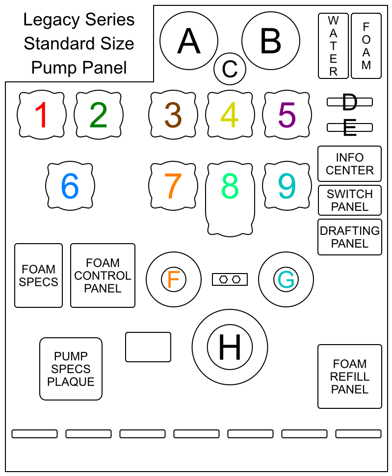
|
Elements | |
|---|---|---|
| A - Master Intake | ||
| B - Master Discharge | ||
| C - Pump Limit | ||
| D - Tank Fill Valve | ||
| E - Tank To Pump Valve | ||
| F - Attack No.1 Discharge | ||
| G - Attack No.2 Discharge | ||
| H - Large Diameter Intake | ||
| Pro-Valves | ||
| 1 - Crosslay No.1 | ||
| 2 - Crosslay No.2 | ||
| 3 - Bumper Line | ||
| 4 - Rear No.1 | ||
| 5 - Rear No.2 | ||
| 6 - Supply No.1 | ||
| 7 - Attack No.1 | ||
| 8 - Deckgun | ||
| 9 - Attack No.2 | ||
5.3.2 Indicators
Master Intake & Discharge Gauge
The Master Intake Gauge will display all incoming water flow in GPM.
Additionally it will indicate the pressure in PSI.
Drafting Operations will produce a negative pressure.
The Master Discharge Gauge will display all outgoing water flow in GPM.
Additionally it will indicate the pressure in PSI.
Additionally it will indicate the pressure in PSI.
Drafting Operations will produce a negative pressure.
The Master Discharge Gauge will display all outgoing water flow in GPM.
Additionally it will indicate the pressure in PSI.
Pump Limit Gauge
The Pump Limit Gauge will indicate how close the Pump is to its maximum flow.
If the maximum flow is exceeded then the Pump will automatically shutdown to prevent any damage.
Incoming pressurized water flow will increase the rated Pump Limit.
If the maximum flow is exceeded then the Pump will automatically shutdown to prevent any damage.
Incoming pressurized water flow will increase the rated Pump Limit.
Water and Foam Level Indicators
The Water Level Indicator will show the fill level of the Water Tank.
An audible warning with an info message in local chat will be given when the Water Tank Level is low.
An additional Water Level Indicator is mounted on the side of the cab.
The Foam Level Indicator will show the fill level of the Foam Cell.
An audible warning with an info message in local chat will be given when the Foam Cell Level is low.
Info Center
The Info Center will display status messages.
'Legacy Series' and 'Fire System 2' will be displayed if the pump is fully operational.
'No Power'
'Pump Error'
'Warning'
'Legacy Series' and 'Fire System 2' will be displayed if the pump is fully operational.
'No Power'
If the Pump Power Shift is set to Pump but the Pump fails to fully engage then 'No Power' will be displayed.
The second line on the Info Center indicates the reason for the lack of power:
The second line on the Info Center indicates the reason for the lack of power:
- 'Start Engine' - Diesel Engine is not running, set Ignition to on and then press Engine Start switch.
- 'Shift Gear to 4' - Transmission is in wrong gear, switch Gear to D or 4th gear.
'Pump Error'
If a Pump Safety Shutoff was triggered then 'Pump Error' will be displayed.
Additionally the Pump Safety Shutoff indicator will be illuminated on the Pump Switch Panel.
The second line on the Info Center indicates the reason for the Safety Shutoff:
Additionally the Pump Safety Shutoff indicator will be illuminated on the Pump Switch Panel.
The second line on the Info Center indicates the reason for the Safety Shutoff:
- 'Tank Valve' - the Tank To Pump Valve is closed and the pump has insufficient water supply
- 'Pump Limit' - the Pump Discharge has exceeded the available Pump Limit
- 'Tank Empty' - the Water Tank is empty and no other sufficient water supply is available
- 'No Water' - the Pump Discharge exceeds the Pump Intake
'Warning'
If a situation arises that requires the pump operators attention then 'Warning' will be displayed.
An audible warning sound is played and the warning message will be shown for 5 seconds.
The second line on the Info Center indicates the reason for the Warning:
An audible warning sound is played and the warning message will be shown for 5 seconds.
The second line on the Info Center indicates the reason for the Warning:
- 'Water Low' - the water tank has less than ¼ remaining
- 'Foam Low' - the foam cell has less than ¼ remaining
- 'Fuel Low' - the fuel tank has less than ⅒ remaining
5.3.3 Controls
Modular HUD
All of the pump controls are also available via the HD Modular HUD.
This requires Version 2022.09.26 or newer of the HUD.
The HUD will automatically sync and open the pump controls tab while 'sitting' on the pump panel.
Individual discharge controls are only shown on the HUD while a hose line is deployed.
The Info Center, Pump Limit Gauge, Foam Master Panel and Foam Refill Panel can be shown/hidden with the tabs on the bottom of the HUD.
Switch Panel
Panel Light
The Panel Light is mounted on the top of the pump panel and will illuminate the area.
The Panel Light is automatically turned off when the Pump Power Shift is set to Road.
Gauge Back LightsThe Panel Light is automatically turned off when the Pump Power Shift is set to Road.
This will activate the Back Lights for all pump controls.
The Back Lights are automatically turned off when the Pump Power Shift is set to Road.
Airhorn
This will activate the Airhorn for as long as the switch is depressed.
It can be used to alert nearby Firefighters of a dangerous situation.
Pump EngagedIt can be used to alert nearby Firefighters of a dangerous situation.
The Pump Engaged indicator will illuminate when the Pump Power Shift is set to Pump.
It also requires the Diesel Engine to be running and the Transmission set to D or 4th gear.
Pump Safety ShutoffIt also requires the Diesel Engine to be running and the Transmission set to D or 4th gear.
The Pump Safety Shutoff indicator will illuminate if the Pump has encountered a dangerous condition.
The Safety Shutoff will be triggered to prevent any damage to the Pump.
The Info Center will show additional information and provide the reason for the Safety Shutoff.
Reset Pump ShutoffThe Safety Shutoff will be triggered to prevent any damage to the Pump.
The Info Center will show additional information and provide the reason for the Safety Shutoff.
When a Safety Shutoff has been triggered then the Reset Switch can be used to continue normal operation.
The dangerous condition should be fully resolved before pressing the Reset Switch.
The dangerous condition should be fully resolved before pressing the Reset Switch.
Draft Panel
Overview
The Draft Panel is used for all Water Drafting Operations.
Drafting is only available if a Suction Hose has been connected to one of the Large Diameter Intakes.
The Drafting System for the Legacy Pumper has been completely redesigned with the update to Version 2022.08.01
It works fundamentally different than on the NextGen Series, the Titanium ARFF Series and the One Series Fire Apparatus.
Controls
The + INC Button will increase the amount of water that is drafted.
The - DEC Button will decrease the amount of water that is drafted.
The Pull to Prime handle will evacuate air from the pump and create a vacuum in order to suction water.
You have to click and hold the Pull to Prime handle until a vacuum has been created.
The amount of time will depend on the amount of strain the pump has to overcome.
If the strain is too high then the pump can not be primed and an info message with the reason will be shown in local chat.
Conditions that prevent priming the pump:
- Drafting Selection set to 0 GPM
- too many Suction Hoses connected
- connected Drop Tank without water in it
- hose line without pressure connected to an intake
- too much elevation gain required for connected suction hose
- combined length of all suction hoses is too long
- too many Suction Hoses connected
- connected Drop Tank without water in it
- hose line without pressure connected to an intake
- too much elevation gain required for connected suction hose
- combined length of all suction hoses is too long
Vacuum Limitations
In order to suction water the pump needs to maintain a sufficient vacuum.
If the vacuum is disturbed then the Drafting Operation will stop immediately and the pump has to be primed again.
Conditions that break the vacuum:
If the vacuum is disturbed then the Drafting Operation will stop immediately and the pump has to be primed again.
Conditions that break the vacuum:
- connecting or disconnecting a hose line to an intake
- hose line connected to an intake loses pressure
- connected drop tank has no more water in it
- reducing Drafting Selection to 0 GPM
- pump triggers emergency shutdown
- hose line connected to an intake loses pressure
- connected drop tank has no more water in it
- reducing Drafting Selection to 0 GPM
- pump triggers emergency shutdown
Drafting GPM
The amount of water that can be drafted is dependent on the amount of strain the pump has to overcome.
Pump Strain Conditions:
Pump Strain Conditions:
- number of connected Suction Hoses (more hoses supply more water with diminishing returns)
- length of all connected Suction Hoses (longer hoses supply less water)
- required elevation gain for all connected Suction Hoses (elevation gain supplies less water)
- available elevation loss for all connected Suction Hoses (elevation loss supplies more water)
- pump limit setting (higher pump limit supplies more water)
Tank Fill Valve & Tank to Pump Valve
The Tank Fill Valve will control the flow of water from the Pump to the Water Tank.
The maximum fill rate is 750 GPM. Any additional incoming water will go through the Overflow Valve.
The Tank to Pump Valve will control the flow of water from the Water Tank to the Pump.
The maximum transfer rate is 500 GPM due to the limited size of the connecting pipe.
It is recommended to use the Water Tank only for the initial attack operations.
A hydrant should be secured in order to utilize the Deckgun.
Pump Overflow Valve
The HD Legacy Pump is equipped with an Overflow Valve.
Any incoming water that can not be utilized by the pump will be discharged through the Overflow Valve.
The overflowing water will be visible and splashing below the pump panel.
Any incoming water that can not be utilized by the pump will be discharged through the Overflow Valve.
The overflowing water will be visible and splashing below the pump panel.
5.3.4 Connections
Intakes
The Legacy Pumper is equipped with five intakes.
Front Bumper - Large Diameter Intake
Pump Panel, Driver Side - Large Diameter Intake
Pump Panel, Passenger Side - Small & Large Diameter Intake
Box Rear - Large Diameter Intake
Front Bumper - Large Diameter Intake
Pump Panel, Driver Side - Large Diameter Intake
Pump Panel, Passenger Side - Small & Large Diameter Intake
Box Rear - Large Diameter Intake
Discharges
The Legacy Pumper is equipped with eight discharges.
Front Bumper - preconnected Bumper Attack Line
Pump Panel, Driver Side - two Small Diameter Discharges
Pump Panel, Passenger Side - Large Diameter Discharge
Pump Panel, Preconnected - two Crosslay Attack Lines
Box Rear - two Small Diameter Discharges
Front Bumper - preconnected Bumper Attack Line
Pump Panel, Driver Side - two Small Diameter Discharges
Pump Panel, Passenger Side - Large Diameter Discharge
Pump Panel, Preconnected - two Crosslay Attack Lines
Box Rear - two Small Diameter Discharges
5.3.5 Pro-Valves
The Pump Panel has nine HD Pro-Valve Controllers to regulate all Discharges and the Deckgun.
Each Pro-Valve has the following features:
GPM Display
Each Pro-Valve has the following features:
GPM Display
The GPM Display will indicate the flow of water in gallons per minute (GPM).
Four Dashes will be shown if the valve is fully closed.
The Display will turn red if the connected Discharge Valve is closed.
Valve PositionFour Dashes will be shown if the valve is fully closed.
The Display will turn red if the connected Discharge Valve is closed.
The Valve Position Display will indicate the position of the Discharge Valve.
A single red dot will be illuminated if the Valve is fully closed.
Clicking on the Valve Position Display will change the Valve to the clicked position.
The position can be adjusted in 10% increments.
Buttons: DEC / TGL / INCA single red dot will be illuminated if the Valve is fully closed.
Clicking on the Valve Position Display will change the Valve to the clicked position.
The position can be adjusted in 10% increments.
DEC - Decrease the Valve Position by 10%.
TGL - Toggle the Valve Position between fully closed, 50% open and fully open.
INC - Increase the Valve Position by 10%.
Color RingTGL - Toggle the Valve Position between fully closed, 50% open and fully open.
INC - Increase the Valve Position by 10%.
The Color Ring of the Pro-Valve corresponds to the Color Ring on the Discharge.
5.3.6 Deckgun
The Deckgun provides a powerful Master Stream for advanced Fire Suppression.
It can discharge between 250 GPM and 1250 GPM.
It features electric motors to allow easy control from the Deckgun Pro-Valve.
It is mounted on a riser extension that allows it to raise up to 2 feet (0.625m) in order to clear the cab roof.
It can achieve an angle between positive 60° and negative 38° along the horizontal plane.
It can be rotated a full 360° without interruption.
The Nozzle supports both a Straight Stream and Fog Pattern water discharge.
It has the option to discharge Foam Mixture from the Foam Injection System.
It is equipped with an automatic avoidance system to limit the flow of water if the Deckgun is pointed near parts of the apparatus structure.
Pro-Valve Controls
STREAM - change the Nozzle to a Straight Stream.
FOG - change the Nozzle to a Fog Pattern.
RAISE - raise the Deckgun extension
LOWER - lower the Deckgun extension
DPLY / STOW - deploy or stow the Deckgun
◀ - rotate the Deckgun counter-clockwise
▶ - rotate the Deckgun clockwise
▲ - raise the Deckgun angle
▼ - lower the Deckgun angle
Remote ControlFOG - change the Nozzle to a Fog Pattern.
RAISE - raise the Deckgun extension
LOWER - lower the Deckgun extension
DPLY / STOW - deploy or stow the Deckgun
◀ - rotate the Deckgun counter-clockwise
▶ - rotate the Deckgun clockwise
▲ - raise the Deckgun angle
▼ - lower the Deckgun angle
This feature will be added in a future update.
5.3.7 Foam System
Foam Master Panel
The Foam Master Panel controls the Foam Injection System.
Power On/Off
Power On/Off
This will turn the Foam Injection System On/Off.
Master Stream
This will toggle the Foam Injection for the Deckgun.
Flow Meter Display
This displays the amount of Foam Mixture that is being discharged.
Foam Percentage Display
This displays the active Foam Concentrate Injection Rate.
For the current Version the Injection Rate is limited to a fixed amount of 3%.
The Foam System Specification Plaque will list the maximum flow for each injection rate.
+ INC / - DECFor the current Version the Injection Rate is limited to a fixed amount of 3%.
The Foam System Specification Plaque will list the maximum flow for each injection rate.
The INC and DEC buttons will change the Foam Concentrate Injection Rate.
The following rates are available:
0.3%, 0.5%, 1.0%, 1.5%, 2.0%, 2.5%, 3.0%, 3.5%, 4.0%, 4.5%, 5.0%, 5.5%, 6.0%
0.3% through 1.5% will discharge Wetting Agent.
The Wetting Agent will fire Water Bullets with increased fire suppression power.
2.0% through 6.0% will discharge Foam Agent.
The Foam Agent will fire Foam Bullets. 3.0% equals the regular Foam Bullets on the NextGen and Titanium Series.
Rates less than 3.0% will have lower fire suppression power than the regular Foam Bullets.
Rater higher than 3.0% will have higher fire suppression power than the regular Foam Bullets.
Foam Refill Panel
The Foam Refill Panel can be used to refill the Foam Cell directly from HD Foam Jugs.
The connected pump will suction Foam Concentrate at a rate of 7.5 gallons per minute.
That means a standard 10 gallon HD Foam Jug will take 1 minute and 20 seconds to be emptied.
Steps for using the Foam Refill Panel:
The Auto Fill feature will continuously suction Foam Concentrate from the Foam Jug until the Jug is empty or the Foam Cell is full.
The Manual Fill feature will suction Foam Concentrate from the Foam Jug for as long as the button is clicked.
The connected pump will suction Foam Concentrate at a rate of 7.5 gallons per minute.
That means a standard 10 gallon HD Foam Jug will take 1 minute and 20 seconds to be emptied.
Steps for using the Foam Refill Panel:
- make sure the Parking Brake is applied and the Battery Master Switch is set to On
- click on the Foam Refill Hose (yellow hose) in the Driver Side Compartment next to the Pump Panel to grab it
- click on the Foam Refill Panel Port (yellow cap) to connect the Refill Hose
- click on one of the Foam Jugs in the rear Driver Side Compartment to grab it
- click on the yellow hose part of the Foam Refill Hose to place the Foam Jug
- click on the metallic suction wand at the end of the yellow hose of the Foam Refill Hose to insert it into the Foam Jug
- click on the green Power On/Off button of the Foam Refill Panel and confirm it lights up
- click on the blue Auto Fill button of the Foam Refill Panel and confirm it lights up
- wait until the Foam Cell is full or Foam Jug is empty
- click on the Foam Refill Panel Port (yellow cap) to remove the Foam Refill Hose
- detach the Foam Refill Hose from your avatar in order to store it back in the compartment
The Auto Fill feature will continuously suction Foam Concentrate from the Foam Jug until the Jug is empty or the Foam Cell is full.
The Manual Fill feature will suction Foam Concentrate from the Foam Jug for as long as the button is clicked.
Foam Containers
The Foam Cell can also be refilled with the HD Foam Cabinet which is available for free as part of the HD Fire System here.
To use the Foam Cabinet:
- click on one of the yellow Containers to grab it.
- stand next to the Pump Panel of the Legacy Pumper
- click on the attached Foam Container to refill the Foam Cell
To use the Foam Cabinet:
- click on one of the yellow Containers to grab it.
- stand next to the Pump Panel of the Legacy Pumper
- click on the attached Foam Container to refill the Foam Cell
5.3.8 Misc
Specification Plaque
The Specification Plaque lists all parameters of the installed Pump.
The owner of the vehicle can click on the plaque to adjust some of the parameters:
Pump Limit
The owner of the vehicle can click on the plaque to adjust some of the parameters:
Pump Limit
The Pump Limit sets the maximum pumping capacity for the Pump.
It can be adjusted between 750 GPM and 2000 GPM in 250 GPM steps.
Water TankIt can be adjusted between 750 GPM and 2000 GPM in 250 GPM steps.
The Water Tank holds the Water for the initial attack.
It can be set to 500 gal to 1250 gal in 125 gal steps.
Foam TankIt can be set to 500 gal to 1250 gal in 125 gal steps.
The Foam Tank holds the Foam Concentrate for the Foam Injection System.
It can be set to 10 gal to 60 gal in 10 gal steps.
Foam PumpIt can be set to 10 gal to 60 gal in 10 gal steps.
The Foam Pump will inject the Foam Concentrate into the Water Stream of the Pump.
Its capacity limits the maximum amount of Foam Mixture that can be produced and discharged.
The Foam System Specification Plaque will list the maximum flow for each injection rate.
The Foam Pump can be set to 3 GPM to 15 GPM in 3 GPM steps.
Its capacity limits the maximum amount of Foam Mixture that can be produced and discharged.
The Foam System Specification Plaque will list the maximum flow for each injection rate.
The Foam Pump can be set to 3 GPM to 15 GPM in 3 GPM steps.
Maintenance Cover
The Pump Maintenance Cover gives access to the Cab Tilting Controls.
Instructions for the Cab Tilting Procedure are mounted next to the controls.
Safety Disconnect Switch
Instructions for the Cab Tilting Procedure are mounted next to the controls.
Safety Disconnect Switch
The Cab Tilt Switch is only functional if the Disconnect Switch is in the 'Active' position.
This is to ensure against accidental operation and personal injury.
Cab Tilt SwitchThis is to ensure against accidental operation and personal injury.
The Cab Tilt Switch controls the tilting operation for the Cab.
If the Master Battery Switch is turned on then the Cab Raise is done in a single step.
If no power is available then the Tilting has to be done manually and each click on the switch will raise the Cab a limited amount.
Once the Cab has reached its maximum Tilt Angle then the Safety Disconnect Switch will be automatically set to 'Disconnect'.
Tilting the cab back down will always be done in a single step as it is gravity assisted.
Scene Lights
The Pump Panel has an extendable Scene Light mounted on either side.
Clicking on the Scene Light Pole will extend the Scene Light Upwards.
Clicking on the Scene Light Lens will switch the Scene Light On/Off.
Clicking on the rear of the Scene Light Housing will show green Control Arrows.
The Control Arrows can be clicked to change the angle of the Scene Light.
Clicking on the rear of the Scene Light Housing again will hide the green Control Arrows.
Refill Towers
The Refill Towers are located on the top of the apparatus behind the Pump Panel.
The blue Refill Tower is connected to the Water Tank.
The yellow Refill Tower is connected to the Foam Cell.
The Refill Towers are compatible with the HD Refill Pipes which are available for free as part of the HD Fire System here.
To use the Refill Tower:
The Refill Towers are compatible with all versions of the Refill Pipes.
Using a Refill Pipe [v2022.08.01] or newer will adjust the Water and Foam Concentrate particle size to match the size of the Refill Towers.
The blue Refill Tower is connected to the Water Tank.
The yellow Refill Tower is connected to the Foam Cell.
The Refill Towers are compatible with the HD Refill Pipes which are available for free as part of the HD Fire System here.
To use the Refill Tower:
- make sure the Parking Brake is applied and the vehicle is within range of the Refill Pipe
- click on the Refill Tower Hatch to open it
- click on the Refill Pipe and select 'Activate' in the menu
- wait until the Refill Pipe is no longer flowing Water or Foam Concentrate
- click on the Refill Tower Hatch to close it
- click on the Refill Tower Hatch to open it
- click on the Refill Pipe and select 'Activate' in the menu
- wait until the Refill Pipe is no longer flowing Water or Foam Concentrate
- click on the Refill Tower Hatch to close it
The Refill Towers are compatible with all versions of the Refill Pipes.
Using a Refill Pipe [v2022.08.01] or newer will adjust the Water and Foam Concentrate particle size to match the size of the Refill Towers.
Test Gauge Panel
The Test Gauge Panel is only decorative and has no assigned function.
Drain Valves
The Drain Valves are only decorative and have no assigned function.
5.4 Direct Interaction
This vehicle supports Direct Interaction.
The Driver of the vehicle can click on exterior elements to trigger certain functions.
The following features are available:
The Driver of the vehicle can click on exterior elements to trigger certain functions.
The following features are available:
- Left or Right Turn Signal to activate corresponding Turn Signal
- Headlights or Brake Lights to switch Lights On or Off
- Cab and Box Marker Lights to switch Marker Lights On or Off
- High Beams to activate them; will turn On/Off if Headlights are on, otherwise On for as long as clicked
- Flashers, Lightbars, Rotoray or rear Beacons to turn Emergency Lights Master Switch On or Off
- Left, Right or Rear Scene Lights to switch them On or Off
- Traffic Director to toggle different Directional Patterns
- A/C Condenser on Cab Roof to turn dual fans On or Off
- Headlights or Brake Lights to switch Lights On or Off
- Cab and Box Marker Lights to switch Marker Lights On or Off
- High Beams to activate them; will turn On/Off if Headlights are on, otherwise On for as long as clicked
- Flashers, Lightbars, Rotoray or rear Beacons to turn Emergency Lights Master Switch On or Off
- Left, Right or Rear Scene Lights to switch them On or Off
- Traffic Director to toggle different Directional Patterns
Clicking on the two Outer Left Light Sections will activate the Left Directional Pattern.
Clicking on the four Center Light Sections will activate the Warning Pattern.
Clicking on the two Outer Right Light Sections will activate the Right Directional Pattern.
If the corresponding Pattern is already active then the Traffic Director will turn off instead.
- Brow Lights above windshield to switch them On or OffClicking on the four Center Light Sections will activate the Warning Pattern.
Clicking on the two Outer Right Light Sections will activate the Right Directional Pattern.
If the corresponding Pattern is already active then the Traffic Director will turn off instead.
- A/C Condenser on Cab Roof to turn dual fans On or Off
6) Equipment
The HD Gear HUD has to be worn in order to use any of the equipment.
Clicking on equipment in the compartments will grab a copy of the equipment.
The equipment will temp-attach directly to the avatar.
Some of the equipment can only be taken once and will restore to the vehicle when detached while in the same region.
Missing equipment can be restored via: Open Main Menu > 'Options' > 'Restock All'.
7) Chat Commands / Gestures
The vehicle listens on channel 2569 to the active driver.
A pack of compatible gestures is available from the Modular HUD
The following commands are supported:
A pack of compatible gestures is available from the Modular HUD
The following commands are supported:
Signal Left [Ctrl+Left] = sigL
Signal Right [Ctrl+Right] = sigR
Hazard Lights [Ctrl+Up] = sigH
Camera [1-9] = cam1 - cam9
Next Camera [0] = cam0
Code 2 (lights) [F2] = code2
Code 3 (lights & siren) [F3] = code3
Code 4 (off) [F4] = code4
Park Brake [Space] = hb
Headlight [L] = headlight
Horn [H] = horntap
EM Master Switch [B] = light
Siren Primary [T] = siren1
Siren Secondary [G] = siren2
Siren Manual [Y] = sirentap
Lightbar [Shift+1] = lightbar
Strobes All [Shift+2] = strobe
Strobes Front [Shift+3] = strobeF
Strobes Side [Shift+4] = strobeS
Strobes Rear [Shift+5] = strobeR
Scenelight [Shift+6] = scene
Exit Vehicle [-] = exit
8) Textures
This vehicle comes with full templates for the cab and box.
The templates are available online: HD Templates
The cab and box textures have to be saved as JPG in order to display properly.
Custom paintjob textures can be applied by using the Legacy Customize HUD.
A copy of Legacy Customize HUD is inside of the Legacy Pumper Delivery Box.
All decal textures have to be saved as PNG with a full transparent background.
Decals can be cleared by leaving the input field blank.
To apply a custom decal texture please use the 'Decal Mode' button in the 'Customize' Menu.
9) HD Theme Box 3
This feature will be added with a future update.
10) Script API
This vehicle comes with a simple Script API.
It can be activated via: Open Main Menu > 'Options' > 'Script API'
Entering a channel number in the input field will activate the API.
Leaving the input field blank will deactivate the Script API.
Commands are only processed if the source object owner matches the vehicle owner.
The following commands are supported:
The vehicle will reply to each command by repeating it plus an integer for the execution status.
Possible reasons for movement not being successful:
Example:
It can be activated via: Open Main Menu > 'Options' > 'Script API'
Entering a channel number in the input field will activate the API.
Leaving the input field blank will deactivate the Script API.
Commands are only processed if the source object owner matches the vehicle owner.
The following commands are supported:
DEREZ
the vehicle will derez
SET POS;(vector)
the vehicle will move to the given region position
SET ROT;(rotation)
the vehicle will change to the given global rotation
SET POS ROT;(vector) ; (rotation)
the vehicle will move to the given region position and global rotation
GET STATUS
the vehicle will derez
SET POS;(vector)
the vehicle will move to the given region position
SET ROT;(rotation)
the vehicle will change to the given global rotation
SET POS ROT;(vector) ; (rotation)
the vehicle will move to the given region position and global rotation
GET STATUS
the vehicle will report its current status to the sending object
reply: GET STATUS;(integer)ParkingBrake;(integer)PumpMode;(integer)HoseLines;(integer)CableReel
parameters:
reply: GET STATUS;(integer)ParkingBrake;(integer)PumpMode;(integer)HoseLines;(integer)CableReel
parameters:
(integer)ParkingBrake : 0 for Parking Brake not applied, 1 for Parking Brake is applied
(integer)PumpMode : 0 for Pump Power Shift set to Road/Drive, 1 for Pump Power Shift set to Pump
(integer)HoseLines : 0 for no Hose Lines connected, 1 for one or more Hose Lines connecte
(integer)CableReel: 0 for Electric Cable Reel stowed, 1 for Electric Cable Reel deployed
(integer)PumpMode : 0 for Pump Power Shift set to Road/Drive, 1 for Pump Power Shift set to Pump
(integer)HoseLines : 0 for no Hose Lines connected, 1 for one or more Hose Lines connecte
(integer)CableReel: 0 for Electric Cable Reel stowed, 1 for Electric Cable Reel deployed
The vehicle will reply to each command by repeating it plus an integer for the execution status.
Possible reasons for movement not being successful:
- Hose Lines are connected
- Electric Cable Reel is deployed
- Exhaust Removal System is connected
- Electric Charging System is connected
- Target Position is more than 10 meters off region or above 4096m
- Target Position has parcel or region restrictions (object entry rule, prim limit, banned, etc.)
- Electric Cable Reel is deployed
- Exhaust Removal System is connected
- Electric Charging System is connected
- Target Position is more than 10 meters off region or above 4096m
- Target Position has parcel or region restrictions (object entry rule, prim limit, banned, etc.)
Example:
Object sends: SET POS ROT;<128.0, 128.0, 32.0>;<0.0, 0.0, 0.0, 1.0>
Vehicle will reply:
Object sends: GET STATUS
Vehicle will reply:
Vehicle will reply:
SET POS ROT;1 when the move and rotate was possible
SET POS ROT;0 when something hindered the movement
SET POS ROT;0 when something hindered the movement
Object sends: GET STATUS
Vehicle will reply:
GET STATUS;1;0;1;0
interpretation:
interpretation:
- Parking Brake is set (1)
- Pump Power Shift is set to Road/Drive (0)
- one or more Hose Lines are connected (1)
- Electric Cable reel is stowed (0)
- Pump Power Shift is set to Road/Drive (0)
- one or more Hose Lines are connected (1)
- Electric Cable reel is stowed (0)
11) Feedback
Please report all bugs, issues and feature suggestions via:
The HD Website Forms for Suggestions and Bug Reports.
Or Instant Message or Notecard to Lares Carter.
Thank you for your support.
The HD Website Forms for Suggestions and Bug Reports.
Or Instant Message or Notecard to Lares Carter.
Thank you for your support.